Signal pulses from a surface barrier or PIPS detector can usually best be read out using a charge sensitive preamplifier (CSP). This is due to the low noise characteristics of CSPs, as well as the integrating nature of the output signal which provides an output proportional to the total charge flowing from the surface barrier/PIPS detector during the pulse event.
Connecting a Surface Barrier or PIPS Detector to the CSP:
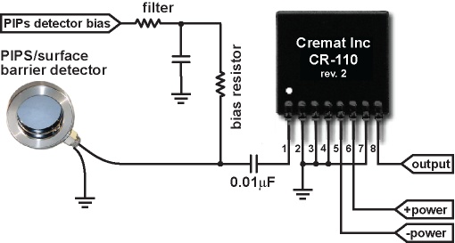
The usual connection scheme of a surface barrier/PIPS detector to the CSP is shown below, and is known as an 'AC coupled' circuit:

Cremat's CR-150-R6 evaluation board uses AC coupling to connect the surface barrier/PIPS detector to the CSP module input.
The charge sensitive preamplifier (CSP) shown in the figure above is shown as an 8 pin module. Cremat offers four different CSP modules (CR-110, CR-111, CR-112, and CR-113) which differ primarily by their gain. A more detailed description of these preamplifier modules can be found here. Surface barrier detectors or PIPS detectors will likely be best served by the CR-110, which has the lowest noise and greatest gain of the available models.
A Surface barrier / PIPS detector based setup
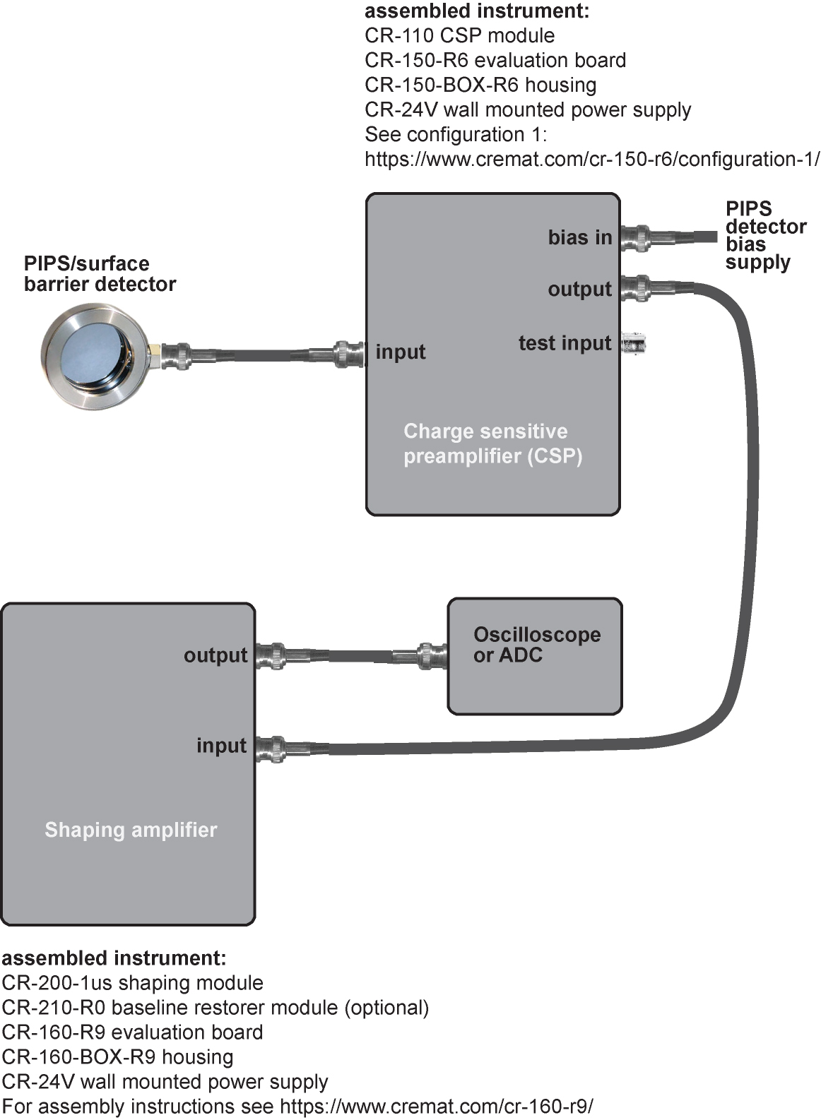
An overview of the instrumentation for a surface barrier or PIPS detection setup is shown below. To preserve low noise operation, we highly recommend keeping the cable between the detector and CSP as short as possible.

helpful links:
https://www.cremat.com/cr-150-r6/configuration-1/
https://www.cremat.com/cr-160-r9/
Choice of shaping time in the shaping amplifier
In the diagram above, the shaping amplifier uses a 1 microsecond shaping time, and is a 'middle of the road' choice for many applications. There are, however, some guidelines to help you determine the best shaping time for your application:
1) Chose the shaping time that will give you a minimum of electronic noise. As was mentioned above, shaping amplifiers are electronic (band pass) filters - the shaping time is related to the band pass frequency. There are a few sources electronic noise in a typical detection system, and some of them differ in their power spectra. While it is outside the scope of this guide to quantify the total electronic noise or provide complicated formulae for calculating the noise minimum, there generally is a noise minimum within the range of available shaping times. Changing the shaping time is a simple matter of swapping out the installed CR-200-X shaping amplifier module for that of another shaping time, so determining the noise minimum could be done experimentally.
2) Choose a shaping time that is short enough to accommodate the expected counting rate of the detection system.